Nullam dignissim, ante scelerisque the is euismod fermentum odio sem semper the is erat, a feugiat leo urna eget eros. Duis Aenean a imperdiet risus.
Nullam dignissim, ante scelerisque the is euismod fermentum odio sem semper the is erat, a feugiat leo urna eget eros. Duis Aenean a imperdiet risus.
 author
An HMI may respond to every tap with a motor stopped, then ignore the same finger as soon as the motor runs. The operating state is a lead, rather than a diagnosis. The motor or charger might disturb the touch electronics, pull down a shared supply, or coincide with an application problem. Buying a more “noise-resistant” screen before separating those paths can leave the fault in place. Watching what happens to input, alongside the rest of the HMI, helps distinguish those possibilities before the installation is changed. For the sensing discussion here, the panel must be projected-capacitive; do not apply that explanation to a resistive panel without checking its technology.
A missed button press does not show whether the finger went undetected or its reported position went unprocessed. The picture, touch controller, and application can fail independently.
An updating process value or animation suggests the display is still being refreshed. A static picture proves less: an LCD can continue showing its last frame while the host has stalled. Where diagnostic access exists, compare the application’s behavior with touch events received by the host. Events arriving while a button does nothing point toward application handling. Missing or implausible coordinates move the investigation toward the touch path, including its controller and connection.
The distinction matters with display assemblies. The LCD and touch functions may have different power and signal paths even though the operator sees one front panel. A black image, a lost USB device, and false finger coordinates should not all be entered in a fault report as “touch stopped.”
A touch controller that resets during motor startup may disappear briefly and return after initialization. That differs from a controller that remains connected but reports no valid contacts. Host device logs, reset information, or supplier diagnostic tools may distinguish them. A shared supply disturbance can affect either path; a working backlight does not rule it out.
“Fails when running” needs a little more detail. A failure at the switching instant and one that persists throughout operation give different leads.
Continuous running may be harmless even though startup interrupts touch. Acceleration and stopping can produce different behavior again, so “motor on” is too broad a description of the test condition. A charger may already be connected when it begins delivering charging current. If stopping the load restores touch, another controlled run of that transition helps establish whether the association recurs.
False touches can issue commands. Reproduction belongs in a controlled machine state where those commands cannot create hazardous motion. Wiring changes and inspection should follow the equipment’s isolation procedure. That is the setting for any further reproduction of the symptom.
Changing the charger, cable position, and software together may produce a working screen without identifying what helped. A useful comparison keeps the page and touch action the same while changing one permitted condition. A simple touch-test view can expose broken drags or extra contacts more clearly than a busy application. Leave the glass untouched for part of the comparison. Otherwise, extra contacts reported without a finger could be missed.

Once the load association is reproducible, the next question is how the disturbance reaches the touch system. The load itself is only one part of that path.
A projected-capacitive controller is looking for the small capacitance change associated with a finger. A disturbance on the controller’s supply relative to its circuit reference can upset that measurement. The common-mode voltage between the equipment and its surroundings can change with the charger connected. The coupling can become apparent only when a finger contacts the glass, bringing the user into the path. A normal DC reading may miss transient noise and says little about that common-mode path.
Controller-side supply and reset traces, captured by a qualified engineer with appropriate instruments, can show what changes during the transition. A display solution board may be on a different power path from the touch controller, so a measurement at that board may not describe the touch supply. A cleaner approved supply that changes the symptom supports further investigation of that path. That is still not a diagnosis of conducted EMI. A different supply may have altered the grounding or reference as well as its noise. Removing protective earth would make the comparison unsafe; it must stay connected.
The touch tail or interface cable may pass close to a drive cable or switching power stage after enclosure assembly. That proximity provides a possible coupling path from the load wiring to the touch electronics. A photograph preserves the original route if the designer approves a trial with the cables separated. A changed response after rerouting would justify examining that path further. It would not establish that the sensor glass had failed.
The shield connections and chassis bonds need to be compared with the equipment design, rather than improvised during the trial. A piece of conductive foil or a new connection to circuit common changes the electrical arrangement around the sensor. It can affect the capacitance being measured as well as the reference. The operating environment of integrated touch displays includes the surrounding metalwork and complete stack. A loose module on the bench leaves those conditions out.

A filter, cable change, or firmware adjustment is a proposed correction until the original failing condition has been repeated successfully.
Filtering may stop false input but can also make a real drag feel delayed or lose a light contact. Available adjustments must be checked against the installed controller and firmware; the screen size gives no answer. Supplier-supported tuning needs to preserve the intended gestures and any specified glove operation. A demonstration with the motor stopped does not establish that balance under the troublesome load.
The corrected sample should retain the intended cable routing, enclosure, and approved charger or motor configuration. Repeat the operating transitions that caused the fault, including no-touch periods and deliberate drags. Acceptance needs to define how missed input and unintended contacts are assessed, as well as the required response to deliberate operation. Working through a motor cycle provides functional evidence. It does not establish EMC certification, and a component test result cannot be carried over automatically to the finished machine.
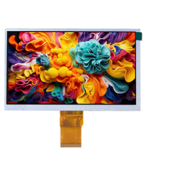
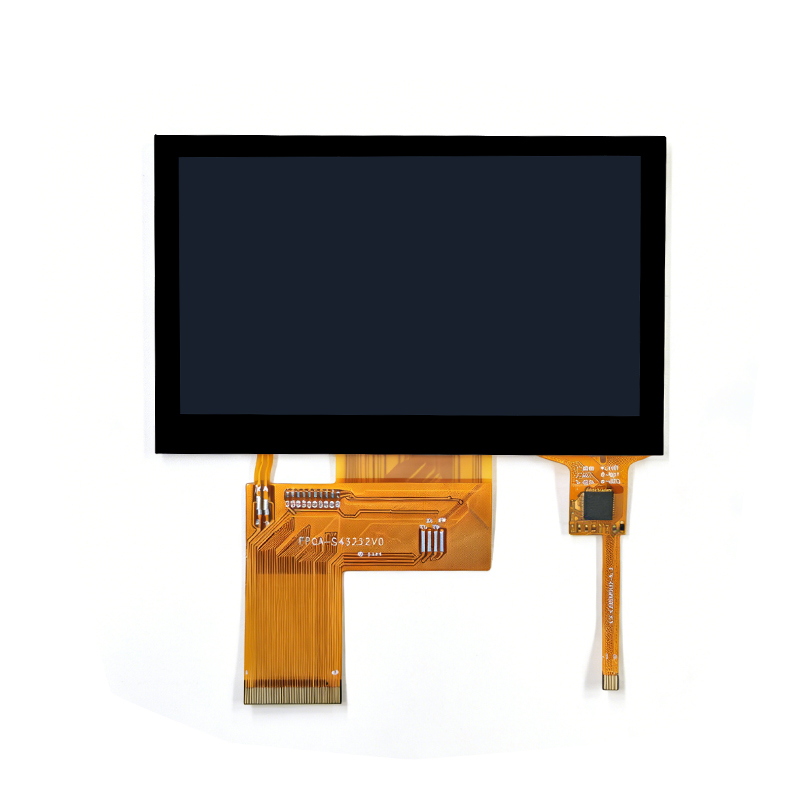
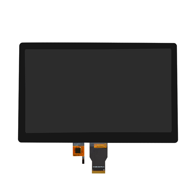
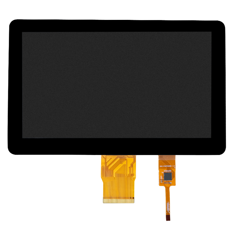
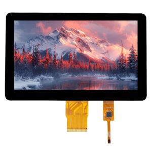
Dongguan SR Optoelectronics Technology Co., LTD. identifies its business as standard and customized LCD display modules. Its 7-inch automotive and industrial touch display assembly is relevant to equipment integration. Before approving a configuration, buyers should confirm the touch technology and controller, supported diagnostic access, and the scope of validation with their actual load and enclosure. A wiring sketch and a reproducible symptom are more useful to that review than a request for an unspecified “anti-interference” screen. The catalog description alone establishes neither a particular controller nor an immunity level.
A motor or charger can reveal a weakness elsewhere in the touch system. Separating lost sensing from resets and application problems gives the load comparison a purpose. The useful endpoint is a corrected installation that survives the previously troublesome operating sequence, with its normal touch functions still usable.
On a battery the charger is absent, but the reference to the surroundings may be different too. The comparison leaves both explanations open. The charger still needs assessment in the approved system arrangement.
Its effect depends on the interference path and frequency. A ferrite will not correct every supply dip, reset, or application fault. The observed failure path should determine whether a ferrite has a useful role.
A response to rerouting gives a reason to pursue the installation path before condemning the glass. It does not establish a defective panel. The revised route still needs validation under the original load conditions and production constraints.