Nullam dignissim, ante scelerisque the is euismod fermentum odio sem semper the is erat, a feugiat leo urna eget eros. Duis Aenean a imperdiet risus.
Nullam dignissim, ante scelerisque the is euismod fermentum odio sem semper the is erat, a feugiat leo urna eget eros. Duis Aenean a imperdiet risus.
 author

The old menu sometimes remains visible as a faint outline after the HMI moves to another page. One question has to be answered before a panel investigation: is the host still including that menu in its output? Long static exposure and the panel’s electrical drive deserve attention once the source has been ruled out. If it is, another screen will receive the unwanted graphic too. If the output is clean and the outline eventually fades, there is still the separate question of what caused it. The answer affects whether buying another module would resolve anything in the equipment.
The shape of the trace offers a starting point. A faint copy of a navigation bar is more informative than a description such as “the display looks bad,” particularly if that bar occupied the same position throughout a shift.
The application may redraw its main page while an overlay still contains the old menu. An overlay or stale frame buffer can leave graphics behind. Where the system permits it, a capture of the outgoing image can be compared with a photograph of the LCD. If both contain the old menu, there is still a host-side problem to resolve.
A clean capture alongside a visible trace on the physical screen shifts attention toward the display. Compatible, independently verified video hardware can help make that distinction when a capture is unavailable. The comparison is useful only if the second source really delivers the intended test image.
An outline matching the previous menu gives the investigation something specific to follow. If a mark has no relationship to the earlier page, its position gives little reason to attribute it to that page’s static exposure. Here the symptom of interest is a recognizable trace of earlier content.
An immediate reboot may clear the screen while also removing evidence. Before changing the operating conditions, save the displayed page and note its dwell time, brightness setting, temperature, enclosure condition, firmware, and module identification.
A uniform mid-gray field makes a useful observation background. The trace may be easier to see at another gray level; patterns used for that comparison should be acceptable to the supplier. The camera can complicate that observation. A change in exposure between photographs changes the apparent contrast of the outline. Keeping exposure fixed and photographing from the same position avoids that ambiguity.
The observation interval belongs in the record too. Without the elapsed time, a reviewer cannot distinguish a photograph of the initial trace from one of the trace after recovery has begun. For its LCD monitors, EIZO suggests a gray display or leaving the power fully off for a period. An industrial module may take a different amount of time to recover. The monitor advice is useful background, but its recovery timing cannot stand in for observations of the module being evaluated under its own supplier instructions.
Taking the machine out of service makes a second comparison possible. Observe recovery with approved changing content, then compare it with recovery after the display has been shut down through the specified power sequence. Backlight shutdown alone leaves that comparison incomplete: a panel may still be driven even though it no longer emits visible light.
On restart, returning to the same neutral test field allows another observation of the contour. The results can be recorded in a compact comparison:
| Observation | What remains to investigate | Next step |
| Old graphic appears in the output capture | Host rendering | Verify the page and overlay output |
| Clean output, fading trace on the panel | Recoverable retention | Repeat the exposure and record recovery |
| Earlier recurrence inside the enclosure | Equipment conditions | Compare matched dwell, temperature, and drive |
| Persistent trace on approved reference hardware | Display module | Preserve the sample for supplier analysis |
These results narrow the investigation. Neither a fading trace nor a successful restart establishes why it occurred, and a recovered sample still needs to withstand the intended HMI duty cycle.

Content history explains which areas were exposed. The approved drive configuration helps explain what electrical conditions the panel experienced during that exposure.
The gray level at a pixel depends on the voltage applied across its liquid-crystal cell. TFT driving normally alternates around the common-electrode reference, VCOM. Texas Instruments explains how residual DC can contribute to image sticking. Its discussion of VCOM compensation and gate drive helps explain why the panel settings belong in this investigation.
A visible trace does not reveal the correct VCOM setting. On TFT LCD modules, those controls are not necessarily accessible to the equipment developer; some are internal or handled by the supplier. Changing an undocumented bias, gamma, or inversion setting means the next observation is made with a different drive configuration. An improvement in appearance after such a change would therefore be difficult to attribute, and another display defect could appear.
A configuration review can start with the panel identification and establish whether its initialization data and controller firmware match the approved combination. A separate display controller solution adds another revision to identify. A qualified engineer needs the panel documentation alongside the measurements to interpret what was captured. An interface designation or a refresh-rate figure does not describe the voltage balance across the liquid-crystal cells.
A moving test video leaves out much of an industrial interface’s exposure pattern. A spinning activity symbol may sit beside a navigation bar that never changes. Qualification should include those stationary regions, with the layout and dwell periods the equipment will actually use.
The interval before recurrence may be different with the display on the bench instead of inside its cabinet. That move can alter conditions other than temperature, so a change in the interval is only a lead. A bench result therefore needs a controlled comparison before it is attributed to heat.
A longer dwell on the cabinet test would make a comparison with the bench difficult to interpret. An exposure of equal duration using the same source page makes the two observations comparable. The location of each temperature measurement matters; an unspecified reading gives no clear basis for comparison. Allowing the conditions to stabilize helps make those readings comparable, while remaining within the display’s approved limits.
Cooling the cabinet and loading new firmware in the same run would leave the team unable to separate their effects. Repeating the run with one of those conditions held steady is what allows the other to be investigated.
Cross-testing can distinguish a module-related result from one confined to the equipment. An approved reference display can be compared on the original host, and the suspect display can be evaluated on compatible reference hardware. The compatibility check comes first: physical size says nothing about matching pinouts or drive conditions.
Behavior that follows the display supports module analysis. Behavior found only in the assembled equipment keeps its operating conditions under investigation. Neither result should be described as a confirmed root cause without the supporting measurements.

Production approval needs to address recurrence. A sample that looks clean after a rest period has demonstrated recovery, rather than suitability for a long static-screen application.
Where operation permits, an idle page, timed content changes, or a screen-saving mode can reduce unnecessary dwell. Required alarms and operator information still have to remain available. Moving a small icon or dimming the backlight may leave the affected areas unchanged, so either measure needs verification through the retention test.
For integrated display assemblies, there is a gap between testing a bare sample and testing it in the enclosure used in production. The test must specify the stationary page and its exposure duration, together with the temperature and brightness at which it is displayed. The subsequent inspection needs its own agreed conditions. A trace photographed immediately on one gray field may look different from the same trace examined later on another field. Those differences make the timing and observation background part of the acceptance agreement, along with the residual visibility that the buyer will reject. The limit has to be chosen for the application rather than borrowed as a supposedly universal value.
A useful supplier submission brings the page capture and photographs together with component revisions, dwell history, temperature measurements, recovery observations, and cross-test results. Keeping the affected unit available lets the investigation continue. Once a controlled correction has been proposed, repeating the same qualification test shows whether it addresses the original condition.
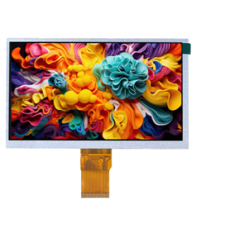
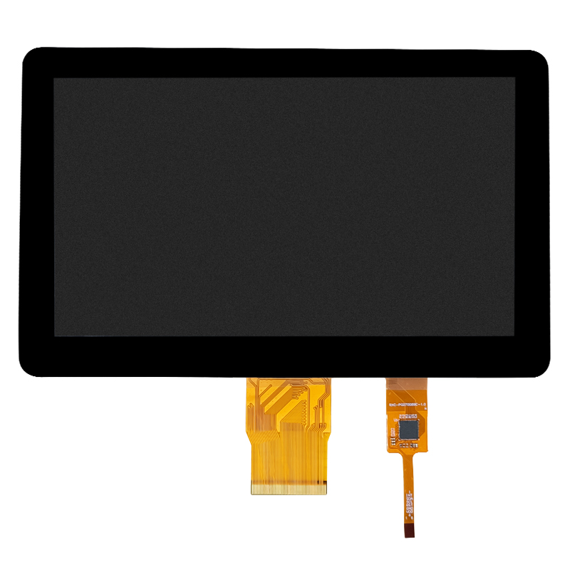
Dongguan SR Optoelectronics Technology Co., LTD. lists TFT displays, solution boards, and display assemblies for equipment projects. Its 10-inch display assembly for industrial HMI is a relevant place to begin a configuration discussion. The intended layout, longest static dwell, enclosure conditions, host information, and proposed acceptance test give that discussion a technical basis. Buyers can then request the current drawing and applicable drive documentation. The catalog’s HMI application description does not establish retention performance; suitability needs to be confirmed for the proposed configuration and operating pattern.
The most useful evidence is the sequence from static exposure to page change and recovery. Establish whether the host output is clean, follow the residual contour under controlled conditions, and investigate drive and enclosure effects separately. A replacement display will face the same static page and enclosure conditions. Until those checks explain the behavior, replacing the module alone remains an uncertain remedy.
An outline that gradually disappears is evidence of recovery. A persistent contour needs further evaluation under the conditions approved for that module. Its visibility alone cannot establish permanent damage or suitability for the intended HMI.
Backlight control and panel drive are separate functions. A recovery test with power removed requires the documented display shutdown sequence, rather than simply making the screen dark.
Only the regions whose displayed content changes have their static exposure interrupted by a screen saver. An animated area beside an unchanged menu leaves that menu exposed. Any change must also preserve access to required alarms and operator information.
Only under an approved engineering procedure. There is no voltage setting that can be read from the shape of the trace. An adjustment made outside the approved supplier procedure changes the test conditions and may hide the behavior that needs explaining.
Pair the contour photograph with the page displayed beforehand and the time that page remained stationary. The recovery timeline and operating conditions give the image context. Component revisions and compatible reference-hardware comparisons can then help narrow the investigation. Retain the affected sample while the investigation is open.