.jpg)
Case Analysis
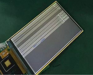
The phenomenon of screen distortion caused by the aggregation of conductive particles in the display module due to high current.
During the bonding process of the display module, an ACF containing conductive particles is used. When the conductive particles in the ACF are heated and compressed, they will burst and expose the metal balls inside. The metal balls are conductors. If they gather together, it will cause a short circuit between two PADs or between lines, resulting in abnormal situations such as large current.
This accumulation of conductive particles is a potential hazard. If no abnormalities are observed during the FOG’s lighting process, display anomalies or high current may appear when playing with the FPC or pressing and bonding the FPC. Generally, the accumulation of conductive particles after bonding occurs in the following two ways:
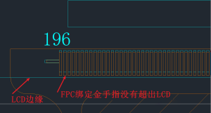
Ⅰ.If the FPC is too wide and covers the ITO traces of the LCD (after the LCD is cut into small pieces, the edge of the LCD will expose the ITO metal part), the conductive particles will accumulate at the boundary where the FPC and the LCD meet, causing a short circuit between the ITO metal parts on the side of the LCD. (The conventional design of the FPC will extend 2-5mm beyond the gold finger target on one side, forming a concave design in the neck bend area to prevent the bonding edge from lifting and falling off when the FPC is pulled.)
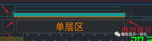
The test lines for some LCD glass are relatively close to the LCD1 target. After the LCD is cut into small pieces, ITO metal remains on the side. If there are no FPC gold fingers at this point when bonding with the FPC, conductive particles can easily accumulate at the junction of the LCD edge and the FPC, causing short circuits between the ITO lines.

For this type of situation, the following suggestions are made:
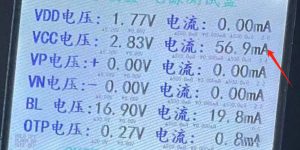
1. During structural design, the distance between the ITO test line and the LCD target should be confirmed using an actual LCD. The design of the FPC’s dimensions relative to the LCD target should also consider the bonding and FPC shape tolerances, while simultaneously incorporating the FPC’s neck bend and concave design to prevent edge pulling and separation. 2. The LCM finished product lighting test fixture should incorporate voltage and current testing to avoid voltage and current anomalies. Multiple voltage and current tests should be conducted to screen out such potential problems and prevent short circuits.
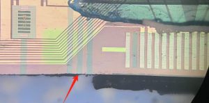
II. During bonding, if the FPC bonding gold fingers are too short, the cover film at the edge of the FPC bonding gold fingers may enter the LCD, creating a step difference that causes conductive particles to accumulate between the bonding gold fingers, resulting in a short circuit.
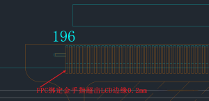
The root cause of this problem is that the length of the FPC bonding gold fingers does not exceed the shape of the LCD. If the bonding gold fingers exceed the shape of the LCD, the FPC is prone to breakage when bent. For this situation, it is recommended to: 1. Extend the FPC bonding gold fingers 0.2MM beyond the edge of the LCD, and after bonding, use a line of silicone to prevent bending the FPC from causing the entire edge of the LCD to break. The line of silicone can also prevent moisture from entering the ACF and causing the bonding FPC air bubbles to fall off.
2. The LCM finished product lighting test fixture after bending FPC should be equipped with voltage and current monitoring to avoid voltage and current abnormalities. Such hidden dangers should be screened out by the upper and lower limits of voltage and current to prevent them from flowing out.