.jpg)
The difference in the location of the display module initialization code within the motherboard driver
The initialization code for the display module is usually placed in the motherboard driver. Some products may be fully programmed using OTP, which eliminates the need to place the corresponding initialization code in the motherboard, allowing for direct plug-and-play functionality. However, it’s important to be aware of the “code-eating” phenomenon mentioned in previous articles.
| The status of the parameter values used by the driver IC is displayed when the initialization code is placed in different locations. | |||
| Driver code architecture | OTP | ||
| Initialization | 11 | ||
| Initialization code | 1129 | Initialization | |
| 1129 | 29 | ||
| Final parameter value state | Depends on the parameter values in the initialization code | Depends on the programming parameters of the OTP | Regardless of whether it has been programmed via OTP, the parameter values still depend on the initialization code. |
If the display module initialization code is placed before 1129, any registers that have been OTP’d will not be overwritten; otherwise, the value in the initialization code will be used. If the display module initialization code is placed between 11 and 29, the initialization code will be used regardless of whether OTP has been performed. This method is generally used to overwrite parameters that still have errors after OTP.
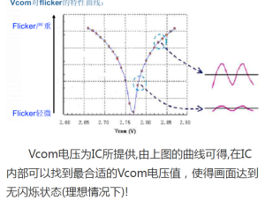
It is particularly important to note that the display module register OTP count is generally limited to 3 times, except for YuChuang’s display driver IC, which can implement unlimited OTP counts. Common OTP values include ID (identity recognition), VCOM (flicker improvement), Gamma (color temperature improvement), and full code (plug-and-play).